
Why the Starter Never Receives the Command to Crank
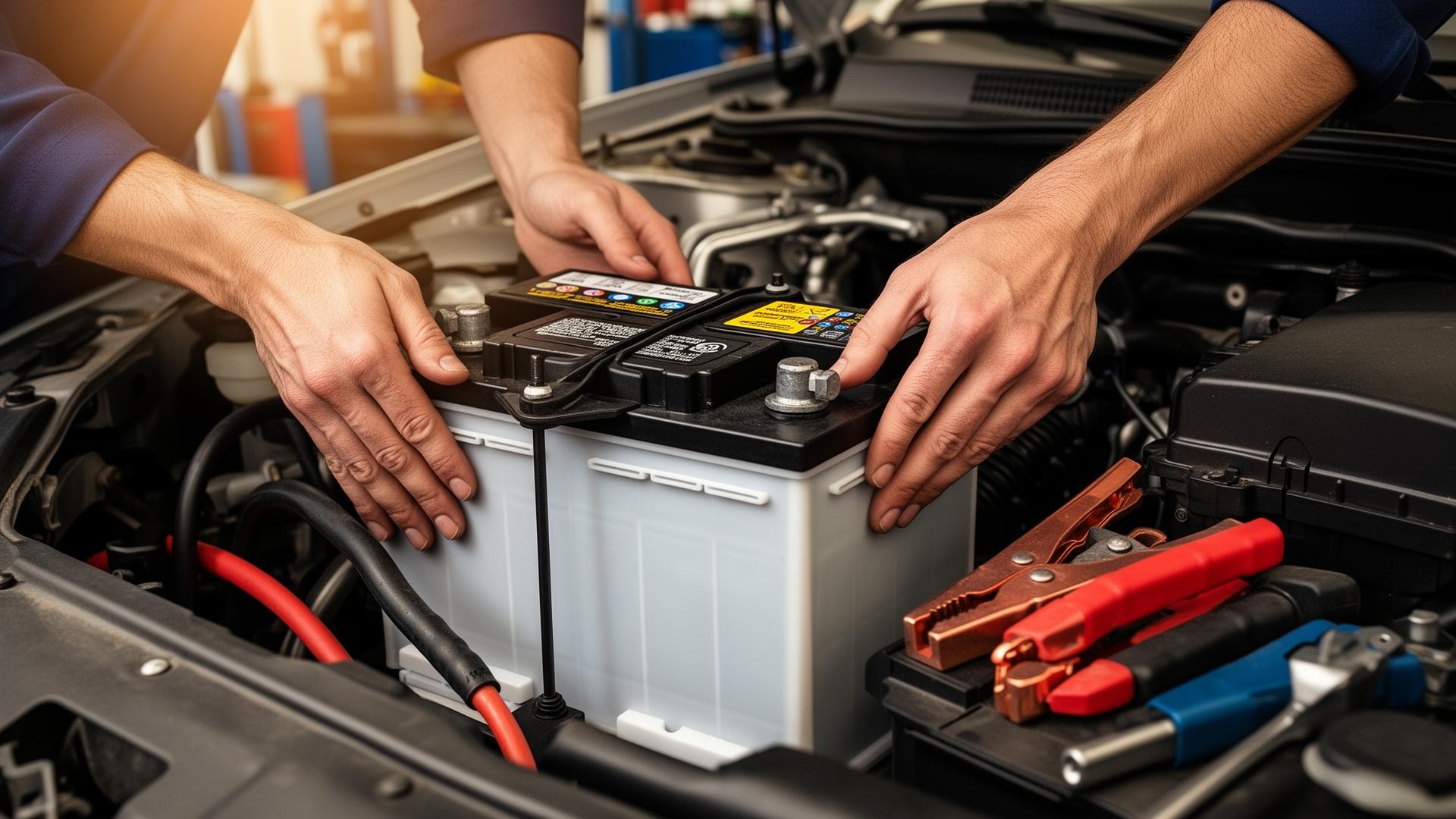
A no-crank condition where the battery tests good and the starter motor has already been replaced is one of the most frustrating electrical problems to diagnose.
At this stage, many vehicles are misdiagnosed repeatedly, parts are swapped, and confidence drops.
In most of these cases, the starter is not failing. It is never being commanded to operate.
This article explains starter control signal diagnosis from an electrical logic standpoint.
You will learn how the starter is authorized to crank, where the control signal travels, why it disappears, and how to confirm the fault using proper testing under real conditions.
Contents
What the Starter Control Signal Actually Is
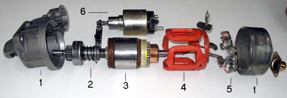
The starter motor does not decide when to crank. It responds to a low-current control signal that energizes the starter solenoid.
This signal:
- Does not carry starter motor current
- Exists only during a crank request
- Must pass through several decision points before reaching the solenoid
If the signal never arrives, the starter remains inactive regardless of its condition.
How Modern Vehicles Authorize Cranking
In older vehicles, the ignition switch directly supplied the starter solenoid. In modern vehicles, starter authorization is conditional.
A crank request typically passes through:
- Ignition switch or push-button start module
- Starter relay
- Neutral safety or clutch interlock
- Body control module or engine control module
- Immobilizer or security logic
Only when all conditions are satisfied does the control signal reach the starter solenoid.
This layered logic is why starter signal faults are often intermittent and difficult to trace.
The Starter Control Signal Path Explained
Understanding the signal path is essential before testing.
A simplified control path looks like this:
- Driver requests crank
- Control module validates conditions
- Starter relay is energized
- Voltage is sent to the solenoid control terminal
- Solenoid engages the starter motor
A failure at any point blocks the entire process.
When the Control Signal Should Appear
The starter solenoid control terminal should receive voltage:
- Only while the key is held in START or the start button is pressed
- Only if interlock conditions are met
- Only for the duration of the crank request
If voltage appears outside this window, a different fault exists.
How to Test the Starter Control Signal Correctly
Testing must be done during an active crank request.
Starter Solenoid Signal Test
- Set the multimeter to DC volts
- Connect the black lead to battery negative
- Connect the red lead to the starter solenoid signal terminal
- Attempt to crank the engine
Interpreting the Results
- Battery voltage present: The control signal is reaching the starter
- No voltage present: The signal is blocked upstream
This single test determines the diagnostic direction.
Why Test Lights and No-Load Tests Can Mislead
A test light can confirm the presence, but not the quality, of the signal.
Common mistakes include:
- Testing with the starter disconnected
- Testing with the relay removed
- Measuring continuity instead of voltage
Control circuits must be tested under real operating conditions.
Common Failure Points in the Starter Control Circuit
Starter signal loss most often occurs at:
- Worn ignition switch contacts
- Faulty starter relays
- Corroded relay sockets
- Failed clutch or neutral safety switches
- Security system authorization faults
These failures do not always set fault codes.

Why Scanners Often Don’t Help
Scan tools report what modules think is happening, not what the circuit is doing electrically.
A module may show:
- Crank request active
- Starter relay commanded
Yet the physical signal never reaches the solenoid due to wiring or relay issues.
Electrical testing confirms reality.
Decision Logic for Starter Signal Diagnosis
Use this logic:
- Signal present at solenoid → Starter or power/ground issue
- Signal absent at solenoid → Trace upstream
- Signal intermittent → Heat, vibration, or relay failure
Never replace parts without locating the signal loss.
Common Misdiagnoses in No-Crank Conditions
These errors are frequent:
- Replacing starters repeatedly
- Condemning batteries without load testing
- Suspecting ECU failure prematurely
- Ignoring ground integrity
Starter control signal testing prevents these mistakes.
Where This Fits in the No-Start Diagnostic Process
Starter signal testing should occur after:
- Battery condition is verified
- Engine and chassis grounds are confirmed
If both are good, control logic is the remaining variable.
👉 Related reading:
Conclusion
A starter that never cranks is often innocent.
When the control signal is blocked, the starter never receives permission to operate.
Understanding how that signal is generated, authorized, and delivered removes confusion from no-crank diagnosis.
Electrical systems follow logic.
When you test the control circuit under real conditions, the fault reveals itself without guessing or unnecessary parts replacement.

Leave a Reply