
How to Trace Power, Grounds, and Control Signals Step by Step

An Electrical No‑Start Diagnosis is not a mystery. It is a failure in power supply, ground integrity, or control signal logic.
Most no-starts are misdiagnosed because testing starts with parts, not with electrical fundamentals.
This guide is the reference point for diagnosing electrical no-start conditions the way a technician should.
It explains how current is supposed to flow, where it commonly fails, and how to make clear diagnostic decisions before replacing anything.
Contents
Key Takeaway
An Electrical No‑Start Diagnosis is a logic problem, not a mystery.
When power, ground, and control signals are tested in order, the fault always reveals itself.
What Qualifies as an Electrical No‑Start Diagnosis
An electrical no-start occurs when:
- The battery is charged
- The engine is mechanically sound
- The engine does not crank or does not respond
This guide does not cover fuel-only or mechanical failures. It focuses strictly on electrical logic.
The Three Things Every Engine Needs to Crank
Every starter system depends on three fundamentals:
- Adequate power supply
- Reliable ground path
- Valid control signal
If any one of these is missing, the starter will not operate correctly.
Diagnosis is simply the process of identifying which one failed.
Required Tools for Electrical Diagnosis
You do not need expensive equipment.
Minimum requirements:
- Digital multimeter
- Test light
- Basic hand tools
A scan tool helps later, but it is not required to diagnose a no-crank condition.
Step 1: Verify Battery State Correctly
Battery voltage alone proves nothing.
A battery can read 12.6V and still fail under load.
The correct first test is voltage drop testing under cranking load.
👉 Read next: Battery Voltage Drop Testing
This test determines whether current can actually reach the starter.
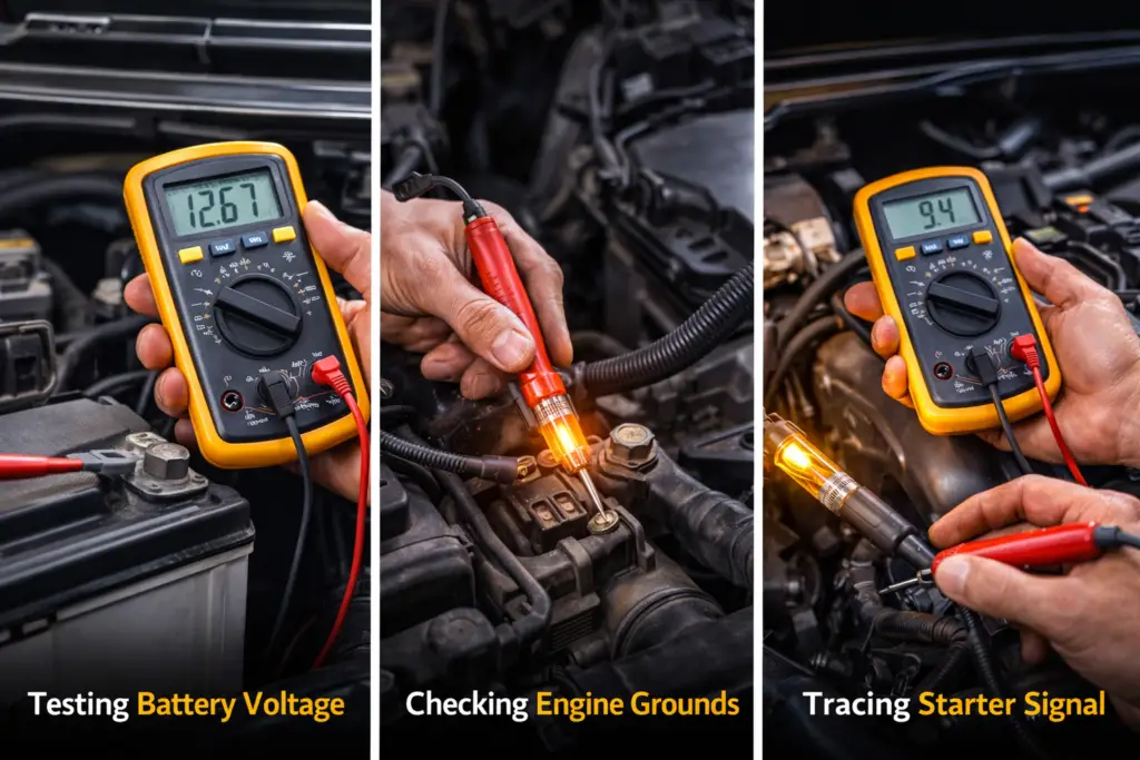
Step 2: Confirm Ground Integrity
Grounds are not optional. They are part of the circuit.
Poor grounds can:
- Disable the starter
- Mimic ECU failure
- Cause random electrical behavior
Ground integrity must be tested under load, not assumed visually.
👉 Read next: Engine Ground Faults Explained
Step 3: Understand the Starter Control Signal
The starter does not engage automatically.
A control signal must travel from:
- Ignition switch or start button
- Through relays, fuses, and safety interlocks
- To the starter solenoid
Loss of this signal results in a no-response condition.
👉 Read next: Starter Signal Path Explained
Step 4: Ignition Switch Electrical Logic
When accessories work but the engine does nothing, the ignition switch is often blamed incorrectly.
The switch must be tested for voltage drop and continuity under load, not guessed.
👉 Read next: Ignition Switch Electrical Failures
Step 5: ECU Power and Wake‑Up Logic
A vehicle can appear completely dead with a perfectly healthy ECU.
Modern ECUs require:
- Constant power
- Switched power
- Proper ground reference
- Network wake‑up signals
Failure in any of these prevents communication and starting.
👉 Read next: ECU Wake‑Up Logic Explained
Common No‑Start Misdiagnoses
These mistakes cause unnecessary parts replacement:
- Replacing batteries without load testing
- Replacing starters without testing cables
- Blaming immobilizers prematurely
- Condemning ECUs without power and ground verification
Electrical diagnosis eliminates guessing.
Diagnostic Order Summary
Follow this order every time:
- Voltage drop testing
- Ground integrity testing
- Starter control signal verification
- Ignition switch evaluation
- ECU power and wake‑up checks
Skipping steps creates false conclusions.
Conclusion
Electrical no-start problems are not random failures. They follow electrical laws every time.
When an engine refuses to crank or respond, the fault always exists in one of three places: power delivery, ground integrity, or control signal logic.
Guessing replaces diagnosis only when these fundamentals are ignored.
This is why parts swapping fails.
A battery can be charged and still be useless under load. A starter can be healthy and never receive a signal.
An ECU can appear dead simply because it never wakes up electrically.
Proper diagnosis means testing the circuit while it is failing, not inspecting it visually or relying on fault codes alone.
Voltage drop testing, ground verification, and signal tracing remove assumptions and force clear decisions.
If you follow the diagnostic order outlined in this guide and work step by step, the fault will always reveal itself before unnecessary parts are replaced.
Electrical diagnosis is not about speed.
It is about logic.
And logic never lies.


Leave a Reply